SPOF mitigation that enters the emergency sequence as a disaster begins
Immediately after an earthquake or wide-area power outage, a facility must confirm the safety of its users while simultaneously checking utility power, gas, communications, roads, water and wastewater systems, and building equipment. At this stage, damage information remains fragmented, and understanding the regional situation takes time.
As several hours pass, information about power outages, communications failures, road closures, fuel supply and personnel availability is shared within the organization. The transition from normal operations to the emergency operating sequence then progresses. Roughly five to twelve hours after the onset is a critical period in which the region and the organization recognize the scale of the damage and decide whether to continue, reduce operations, evacuate or request external support.
IMMEDIATELY AFTER ONSET
Equipment detects abnormal conditions
The system detects the power outage, seismic movement, gas shutoff status, communications condition and generator-start requirements.
FIVE HOURS AFTER ONSET
Facility functions are assessed
Power, fuel, air-conditioning, elevators, communications, water systems and staffing are reviewed to determine which facility functions can continue.
TWELVE HOURS AFTER ONSET
Emergency operations continue
The facility moves into sustained emergency operations, including load management, fuel management, staff rotation, external support and business continuity.
Utility power, fuel, high-voltage receiving equipment, transfer panels, distribution paths, communications, monitoring and staff procedures all support this transition. When dependency is concentrated in one component, the resulting failure can propagate through air-conditioning, elevators, kitchens, communications, monitoring functions and childcare environments.
Such a single failure point is called a SPOF: a Single Point of Failure. A SPOF may be a power device or generator, but it may also be a fuel-procurement route, communications link, transfer procedure, maintenance structure or dependence on a specific staff member.
This project configured utility power and on-site generation, city gas and LP gas, high-voltage receiving and transfer equipment, smart metering and 24/7 monitoring, and automated control and staff operation as multiple independent paths.
Utility-power outage detected
  ↓
LP gas generators start automatically
  ↓
Two generators enter parallel operation
  ↓
Transfer equipment supplies the whole-facility distribution system
  ↓
Smart meters measure the actual load
  ↓
Staff confirm power use and facility functions
  ↓
The facility enters emergency load, fuel and continuity operations
Energy multiplexing activates multiple independent paths from the onset of a disaster, localizes the impact of a single failure and transitions facility functions into the emergency operating sequence.
A 72-hour continuity design triggered by a news report
On January 16, 2019, Yomiuri TV’s “Kansai Joho Net ten.” broadcast a feature titled “Beyond Recovery: The Kobe City Monozukuri Factory,” introducing our work in decentralized and self-reliant power systems.
The Kobe City Monozukuri Factory is a publicly operated rental factory established to support small and medium-sized manufacturers that lost their factories in the Great Hanshin-Awaji Earthquake. The report showed how a site created for post-earthquake recovery had evolved into a base for developing power technologies that preserve social functions during disasters.
After watching the report, the chairman of Masumikai Social Welfare Corporation focused on a specific question: how could the elderly-care facility, day service center and nursery school continue operating during a large-scale power outage?
At the chairman’s instruction, the facility manager contacted our company. The review began with the building’s actual power use, air-conditioning, elevators, kitchens, communications, high-voltage receiving equipment and fuel supply.
Amagasaki and the wider Hanshin region experienced the simultaneous loss of electricity, gas, transportation and communications during the Great Hanshin-Awaji Earthquake. In neighboring areas, including Osaka, the effects and disruption remain part of the region’s shared experience.
Our company representative also experienced the earthquake in Kobe. The project therefore treated 72 hours as the period during which life-supporting facility functions must continue internally before external assistance and fuel resupply can be relied upon.
The resulting design automatically starts the generators when a utility outage is detected, measures the actual facility load and maintains functions such as air-conditioning, vertical transportation, lighting and communications through an energy-multiplexing system.
The report conveyed a design philosophy for continuing everyday facility operations after infrastructure stops.
Protecting three social-welfare services as one whole-facility system
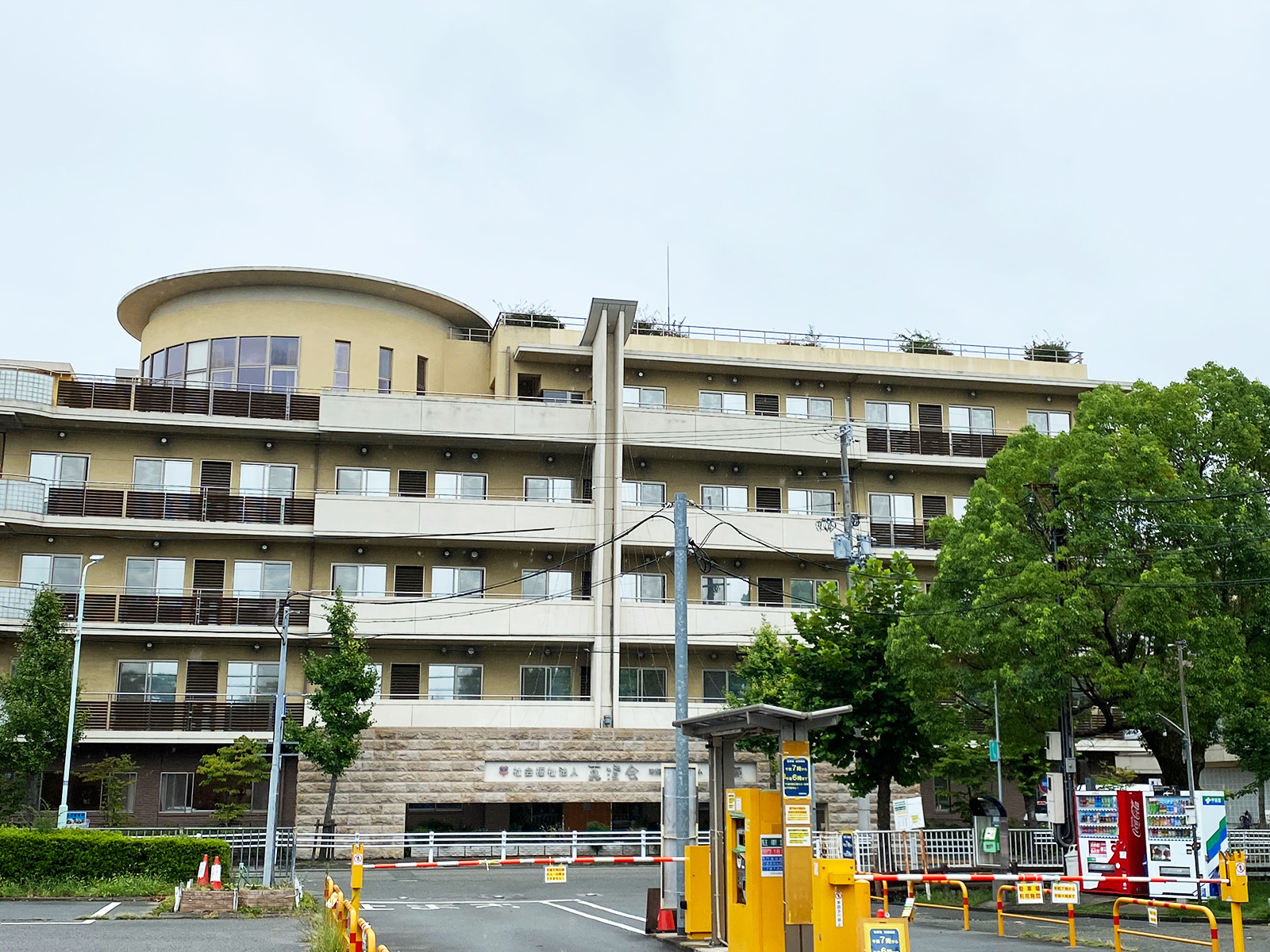
The protected scope covers Hakujuen Special Nursing Home, Sakura Day Service Center and Nishimuko Minori Nursery School. The three services share one site and one high-voltage receiving system and were therefore treated as one operational continuity system.
Elderly-care and childcare operations depend on more than lighting. Air-conditioning, elevators, kitchens, water supply and drainage, offices, communications, monitoring systems and resident or childcare environments must function together.
The backup scope therefore includes the load connected to the existing high-voltage facility system rather than only a limited group of emergency outlets or emergency circuits.
Utility power and existing high-voltage receiving equipment
  ↓
Transfer panel, dedicated transformer and whole-facility distribution
  ├─ Normal operation: utility power
  └─ Power outage: two 54 kVA-class LP gas generators
                     ├─ Parallel operation / total 108 kVA
                     ├─ Automatic startup during an outage
                     └─ 24/7 monitoring
  ↓
Hakujuen Special Nursing Home
Sakura Day Service Center
Nishimuko Minori Nursery School
  ↓
Continuous load and energy measurement by smart meter
Whole-facility backup does not mean that every device can operate at maximum output without limit. The complete facility load is included in the measurement and control scope so that required functions can be maintained within the available generation and fuel capacity.
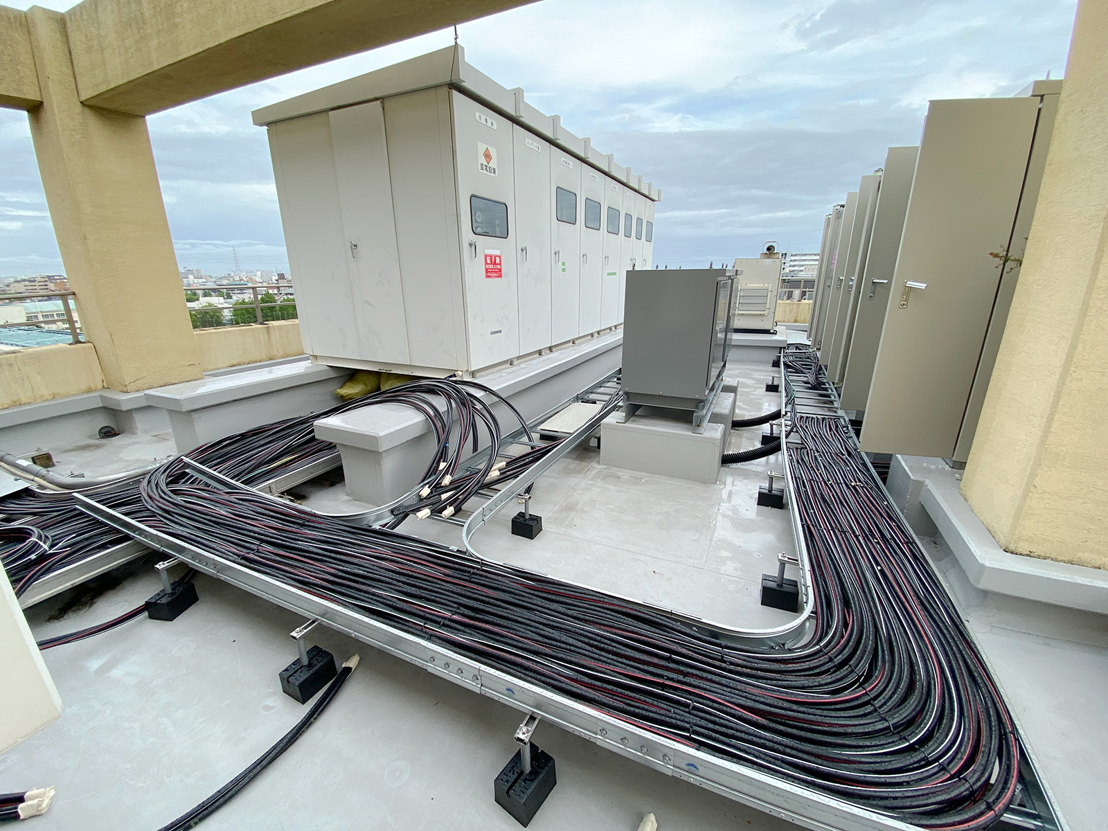
Multiplexing electricity and gas supply paths
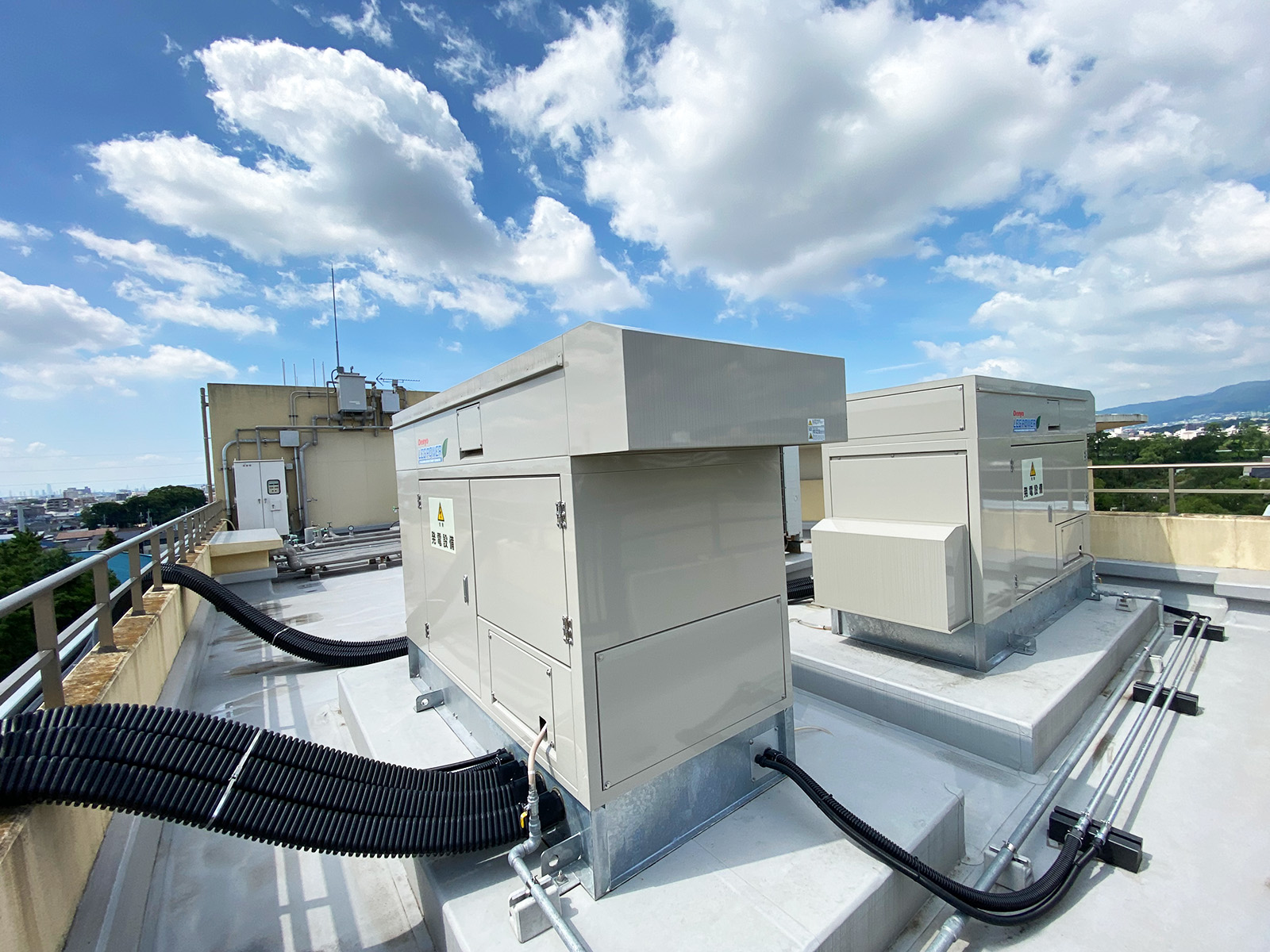
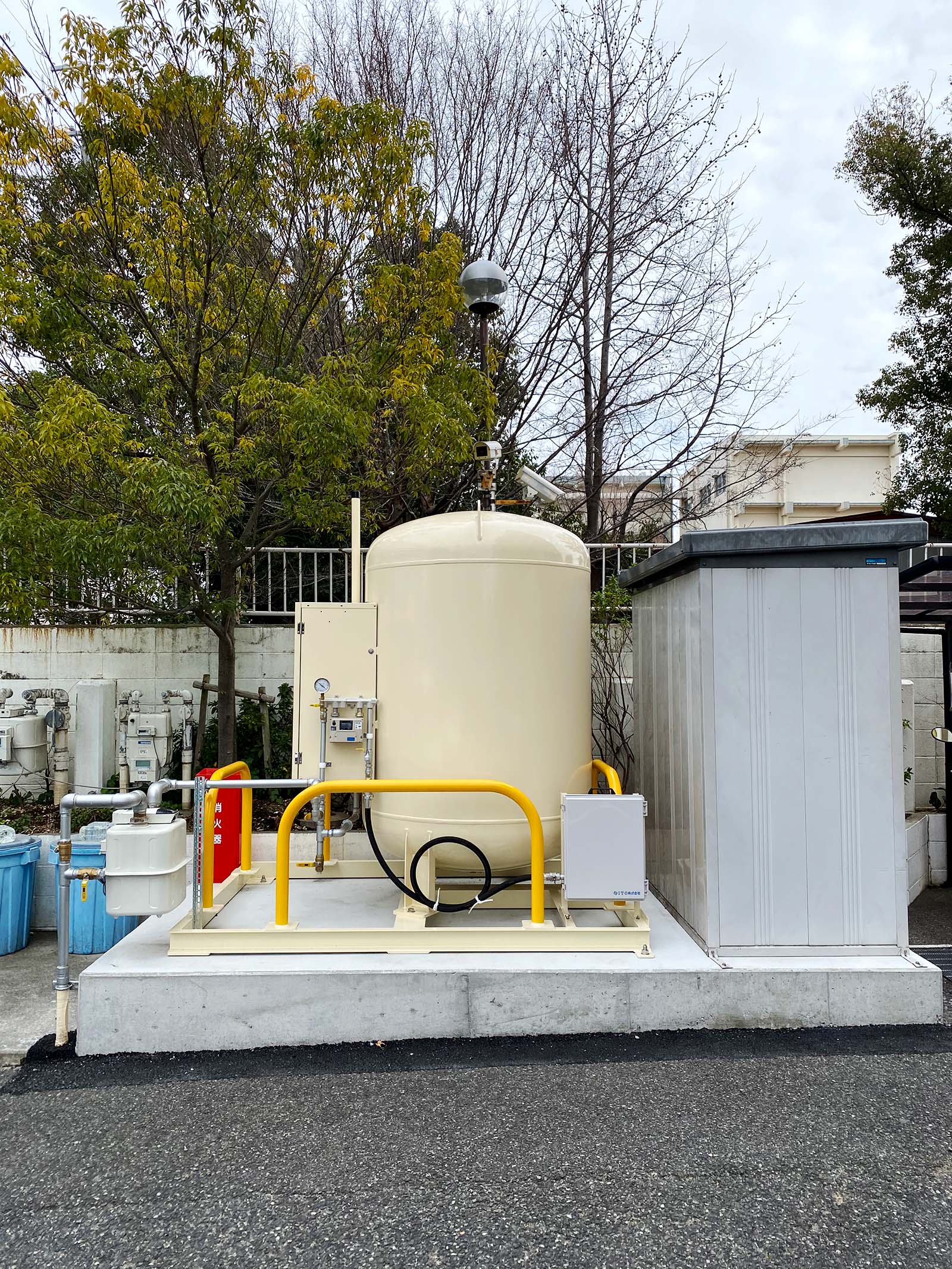
In addition to utility power and city gas used during normal operations, the facility has an LP gas generation system that can produce electricity on site during a disaster.
The electrical system combines utility power supplied by the power company with independent power generated by LP gas generators on the premises. When a utility outage is detected, two 54 kVA-class generators start automatically and enter parallel operation.
The generated power passes through the transfer panel and dedicated transformer into the existing high-voltage receiving and distribution system, supplying the building that houses elderly care, day services and childcare.
For gas supply, the existing city-gas system remains in use during normal conditions, while 980 kg of LP gas for emergency generation is stored in an on-site bulk tank. A regional pipeline network and independently stored fuel therefore provide separate supply paths.
Normal operation
  ├─ Utility power → high-voltage receiving equipment → whole facility
  └─ City gas → normal facility equipment

Utility-power outage
  ├─ LP gas bulk storage tank
  │     ↓
  ├─ Two 54 kVA-class generators
  │     ↓
  ├─ Parallel operation / total 108 kVA
  │     ↓
  ├─ Transfer panel and dedicated transformer
  │     ↓
  └─ Independent power supplied to the whole-facility distribution system

Operations
  ├─ Load measurement by smart meter
  ├─ 24/7 status monitoring
  └─ Whole-facility load management within generation capacity
City gas is supplied efficiently through a regional pipeline network. Following a major earthquake, regional pipelines require safety inspection and staged restoration before service can resume.
LP gas can be held as an on-site fuel inventory. Depending on road conditions and damage to supply bases, alternative suppliers and delivery routes may be selected. Fuel storage and procurement paths are therefore designed together.
Electricity and gas support essential facility functions,
and both can cause serious accidents through electric shock,
short circuits, fire, leakage, gas accumulation or ignition.
Safe operation requires those hazards to be assumed from
the outset and managed through isolation, transfer,
protection, detection, ventilation, inspection,
monitoring and controlled restoration procedures.
In the electrical system, circuit breakers, protection devices, grounding, transfer interlocks and generator parallel-control functions prevent incorrect interconnection, short circuits, overload and reverse power flow.
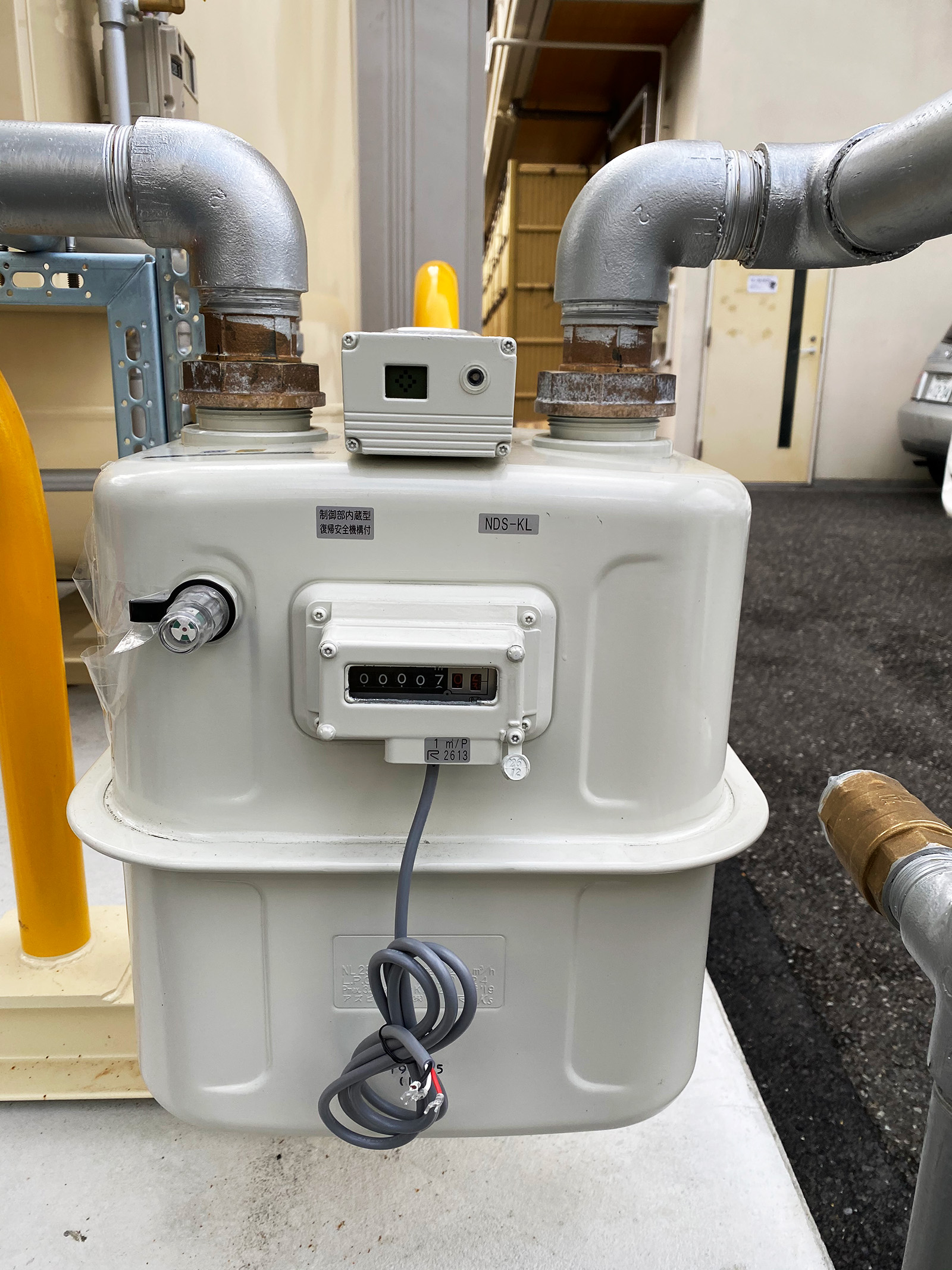
During an outage, the generators start and the power path transfers automatically. Smart meters then show the whole-facility load. Power use is managed within the 108 kVA generation capacity so that air-conditioning, elevators, communications, lighting and other facility functions can continue.
When utility power returns, its voltage and condition are confirmed before the facility transfers from independent generation back to the utility supply. Startup, shutdown, transfer and restoration are managed as one operating sequence.
The 980 kg LP gas bulk storage tank is physically separated from the building occupied by residents and users. This separates the fuel-storage installation from the occupied building’s damage zone and enables inspection, maintenance and refilling to be performed outdoors.
Gas piping is also routed outside the building wherever practicable. Keeping piping visible and accessible supports post-earthquake visual inspection, leak testing, repair and sectional replacement.
The gas-supply meter includes an automatic seismic shutoff function. After a shutoff, the piping, connections, surrounding equipment, gas odor and ventilation condition are checked before the system is restored manually.
Isolating the power supply does not by itself establish a safe electrical condition. Shutting off the gas supply does not remove residual gas. Energy-system operation includes post-isolation inspection and controlled restoration.
Using emergency generators for demand control and disaster drills
A conventional emergency generator may have few opportunities to operate against the facility’s actual load apart from statutory inspections and short test runs.
Operational SPOFs may then remain undiscovered until an emergency: staff may not know the operating procedure, the usable equipment range, the actual fuel-consumption rate or the meaning of an alarm.
At Hakujuen, the generators are started on summer and winter days when the facility forecasts that its contracted demand may be exceeded. The generated power reduces the peak drawn from the utility supply.
This normal-time operation is also treated as a live disaster drill. Staff verify startup, transfer, parallel generator operation, load changes, alarms and fuel consumption under actual conditions.
Forecast a demand peak
  ↓
Start the LP gas generators
  ↓
Reduce the utility-power peak
  ↓
Confirm load, alarms, fuel and transfer status
  ↓
Staff operate the same equipment used during an emergency
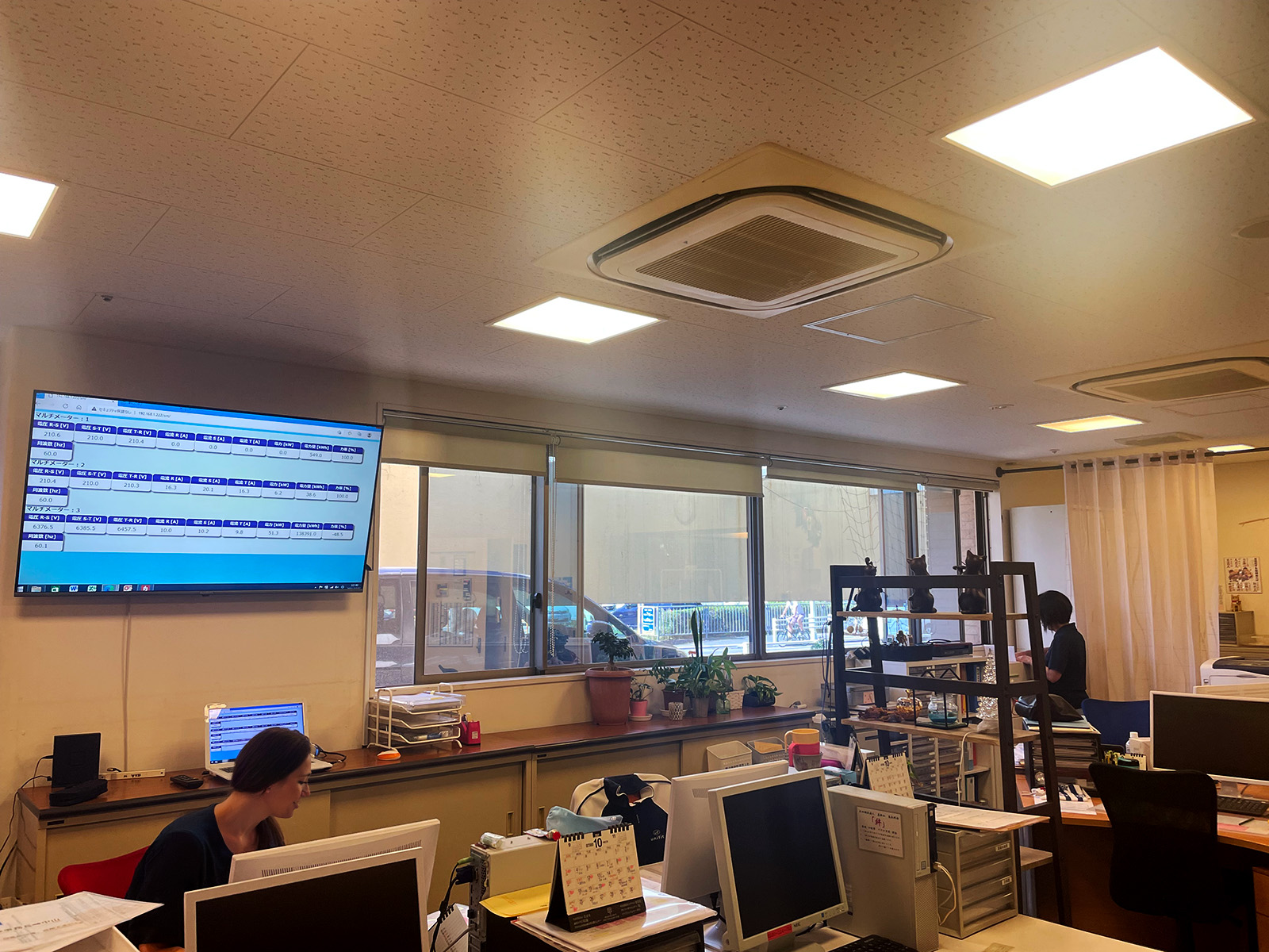
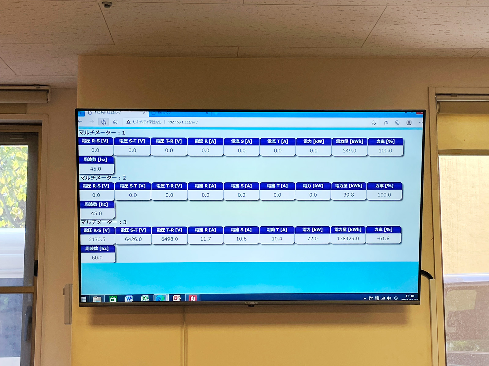
A large monitor in the central office displays smart-meter measurements such as voltage, current, power and energy use in real time.
Power information is shared across the staff rather than being limited to the facility manager. Staff can see how much the facility currently depends on electricity.
Normal-time operation reveals equipment faults, operating errors, dependence on individual personnel, overload and overlooked dependencies before a disaster occurs.
End-to-end implementation of high-voltage equipment, transfer, metering and monitoring
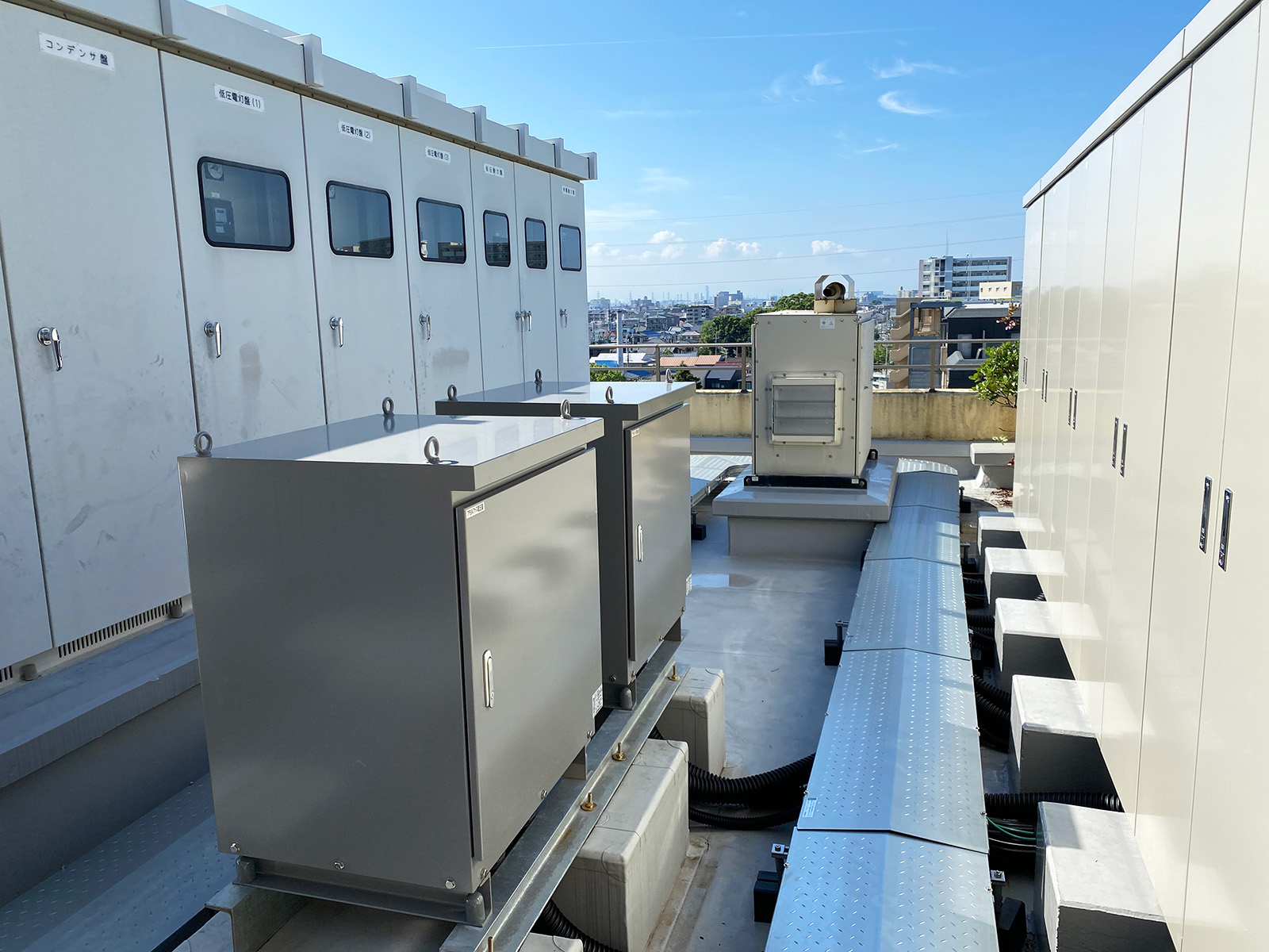
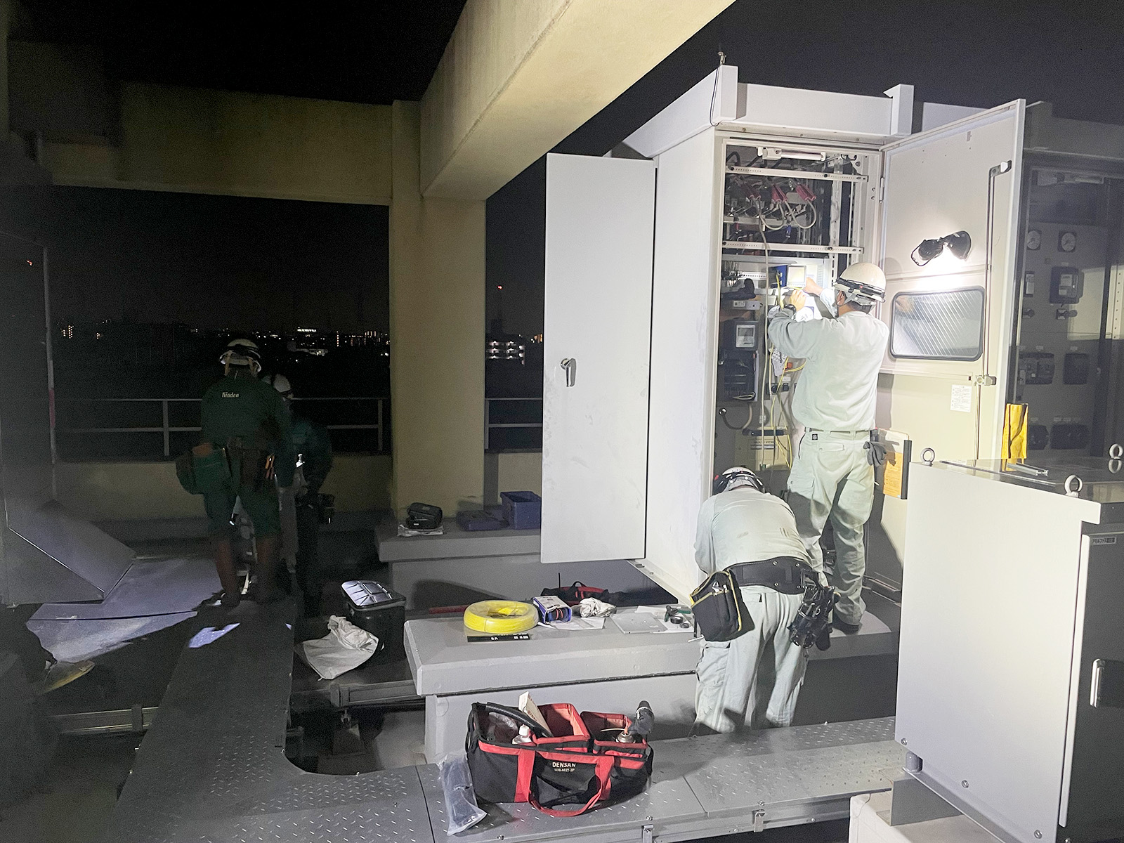
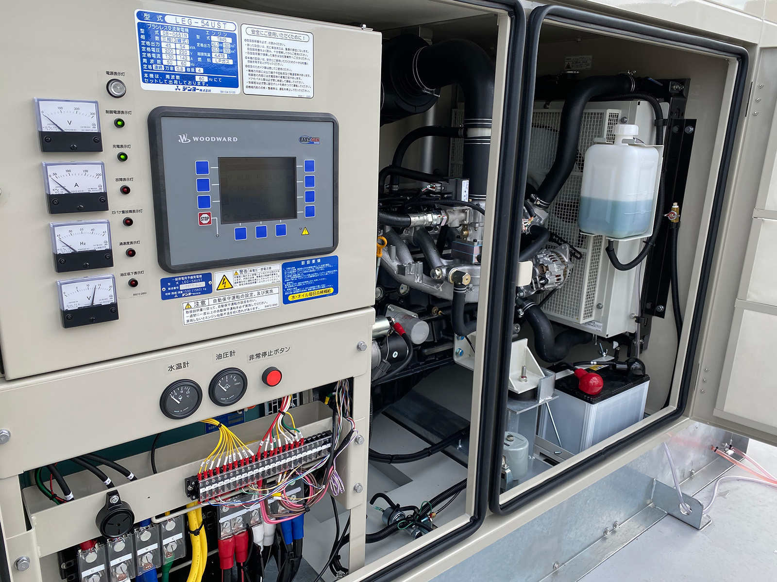
This project covered more than generator installation. The existing high-voltage cubicle, transfer panel, dedicated transformer, rooftop wiring, gas piping, generator parallel control, smart metering and monitoring were designed and implemented as one system.
Generated electricity must be received safely, transferred, transformed and distributed to each facility load. Each stage is required for facility functions to continue.
Because the project covered the existing high-voltage facility load, special construction included rooftop equipment delivery, foundations, electrical wiring, piping, weather protection and maintenance access.
The smart-meter measurement output was branched from the upstream side of the metering point inside the high-voltage cubicle.
A complete nighttime shutdown was scheduled to minimize the effect on facility operations. The actual facility downtime was completed within five minutes.
After commissioning, generator status, electrical load, transfer condition and alarms are monitored 24 hours a day, 365 days a year. Changes during normal operation provide early indications of abnormal conditions.
Editorial Update / August 2026
The 2026 Kumamoto Earthquake Made the Risk Real: A Welfare Facility Unable to Maintain Air Conditioning
During the 2026 Kumamoto Earthquake, an elderly-care facility in Hikawa Town, Kumamoto Prefecture lost power and remained unable to use air conditioning for two days until electricity was restored.
According to reports, most of the approximately 80 residents developed symptoms suspected to be heat-related illness, and more than 20 people were transported for medical care. Water was also unavailable, making it difficult to cool residents. Gas restoration was delayed as well, creating hygiene-management problems because bathing could not resume.
In an elderly-care facility, air conditioning is not merely a comfort system. During extreme heat, it is a critical load for sustaining residents’ lives, alongside medical and care functions.
Emergency power for selected loads alone does not maintain facility continuity
Even if lighting, nurse-call systems and communications remain available, an elderly-care facility cannot maintain its function if air conditioning, water supply, drainage, bathing, kitchens and elevators stop.
BCP therefore needs to be evaluated not by whether an emergency generator started, but by which loads required to sustain residents’ lives and daily living can operate, for how many hours, and under what operating conditions.
The energy-multiplexing system in this case was designed to maintain facility functions, including air conditioning, for at least 72 hours through two generators and smart-meter-based load management when utility power is lost.
The related Japanese article organizes the power outage, water interruption, communications disruption, fuel shortage and degradation of medical and welfare functions observed in the 2026 Kumamoto Earthquake, together with decision points at 5, 24 and 72 hours after onset.
SPOF decomposition and operational design that make 72-hour continuity achievable
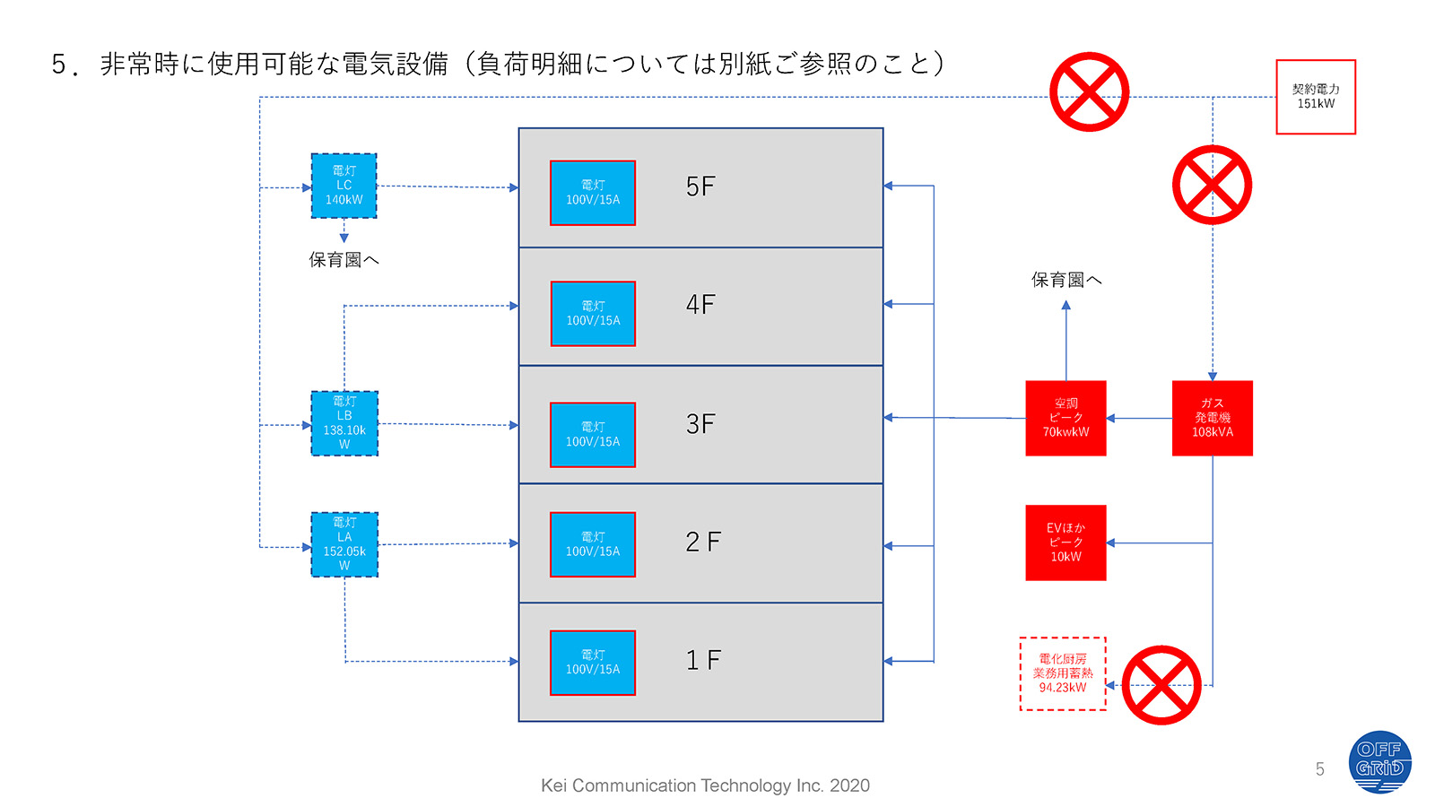
The facility’s contracted demand is 151 kW. Generator capacity was selected from actual operating conditions rather than from a simple total of equipment nameplate ratings. The normal daytime average load of approximately 60 kW was used as the basis for selecting two 54 kVA-class generators with a combined capacity of 108 kVA.
During an outage, smart meters and the monitoring display are used to manage the whole-facility load so that power use remains within the 108 kVA generation capacity.
Within the planned load and operating conditions, the system is designed to maintain air-conditioning, elevators, lighting, office systems, communications and other facility functions for at least three days.
The 2026 Kumamoto Earthquake showed that loss of air conditioning at an elderly-care facility can lead to suspected heat-related illness and emergency transport. For welfare facilities, maintaining the full set of required loads is a life-sustaining BCP requirement, not a matter of convenience.
Storing 72 hours of fuel alone does not establish BCP.
Seventy-two-hour continuity becomes achievable when
the facility understands its load, operates the system
during normal conditions, monitors overload,
plans fuel resupply and enables staff to operate
the equipment.
72 HOURS / TECHNICAL PAPER / JAPANESE
BCP: What Is the Basis for “72 Hours” During a Power Outage?
“72 hours” is neither the time until utility power is restored nor a guarantee of continuous emergency-generator operation. This Japanese-language PDF examines the design required to maintain facility functions for 72 hours through long-duration outage planning, fuel resupply, continuous operation, load management and off-grid power.
Open or download the 72-hour technical paper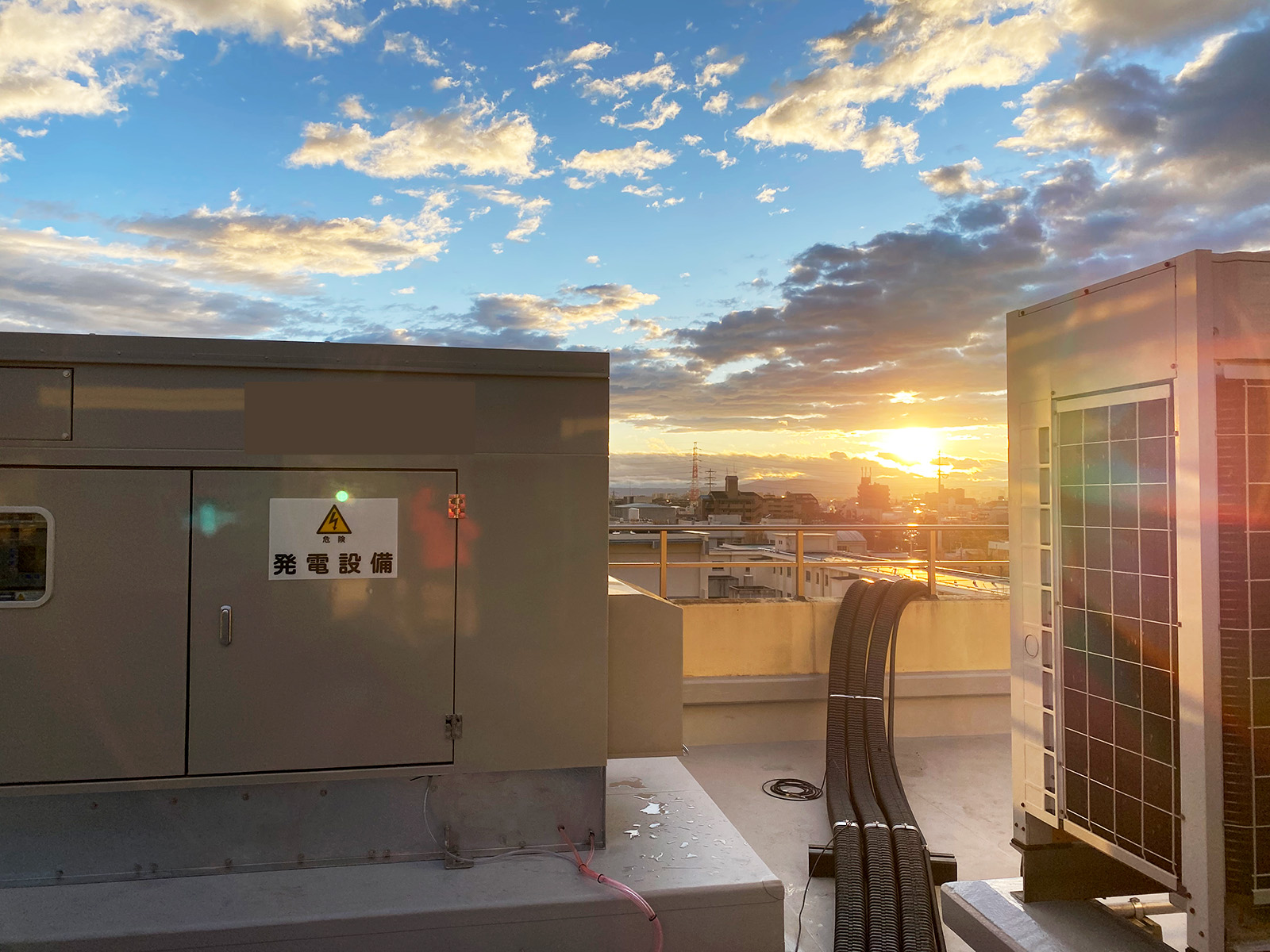
Deployment Summary
| Customer | Masumikai Social Welfare Corporation |
|---|---|
| Facilities | Hakujuen Special Nursing Home, Sakura Day Service Center, Nishimuko Minori Nursery School |
| Commissioned | February 2020 |
| Electrical service | High-voltage service with backup of the existing whole-facility load |
| Generation | Two 54 kVA-class LP gas generators, parallel operation, total 108 kVA |
| Fuel storage | 980 kg LP gas disaster-response bulk storage tank |
| Fuel multiplexing | Existing city gas plus LP gas for emergency generation |
| Transfer | Automatic startup during an outage and whole-facility transfer |
| Normal-time use | Summer and winter demand control and actual-load operation as disaster training |
| Metering | Continuous smart-meter measurement and staff sharing of power use |
| Monitoring | 24/7 monitoring |
| Design concept | Multiplexing utility and on-site power, city gas and LP gas, equipment, monitoring and staff operations |
Revision History
| 2022-04-27 | Published. |
|---|---|
| 2026-08-08 | Latest substantive update of the Japanese source edition before the V9.1 English synchronization. |
| 2026-09-25 | English edition synchronized with the Japanese CaseSpec V9.1 source, including the August 2026 Kumamoto earthquake validation and current evidence and related-article paths. |